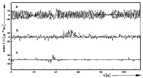
Fig. 8: Typical stretches of three common patterns of yaw torque flight trace. a. Oscillating mode. b. Noise mode. c. Quiet mode. (Redrawn from Heisenberg and Wolf, 1984)
An analog to digital converter transforms the data from the torque compensator measuring the fly's yaw torque into a sequential array of consecutive data points with possible values ranging from -2048 through 2047 (sampling frequency 20Hz). The zero value is adjusted individually for each fly by calibrating the fly's maximum optomotor response to clockwise and counterclockwise turns of the arena to be zero-symmetrical; in the flight simulator this corresponds to flying straight ahead. These raw data are stored in the computer memory (torque trace).

Fig. 8: Typical stretches of three common patterns of yaw
torque flight trace. a. Oscillating mode. b. Noise mode. c. Quiet mode.
(Redrawn from Heisenberg and Wolf, 1984)
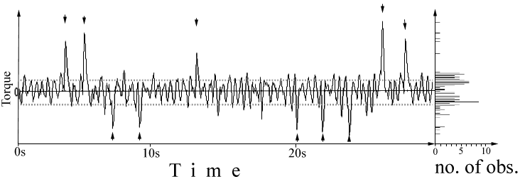
The spike detector used in this work takes advantage of the most prominent feature distinguishing spikes from the torque baseline (optomotor balance): their amplitude. Since the amplitude of the torque baseline is subjected to a considerable amount of inter- and intraindividual variation (Fig. 8), detection thresholds are computed from the torque trace every 600 data points (i.e. 30s of flight): the two peaks of a frequency distribution, gathered by arranging the data points corresponding to maxima and minima in the torque trace according to their frequency, delineate the interval inside which the torque baseline is assumed to lie (Fig. 9).

Fig. 9: Typical stretch of the yaw torque flight trace (left)
with a distribution histogram of the torque maxima and minima (right).
Detected spikes are indicated with arrowheads. Dotted lines denote the
detection thresholds (see text).
A continuous array of 2<n<17 data points of equal sign, the first of which exceeding the torque baseline is then considered a spike if it fulfills the following criteria:
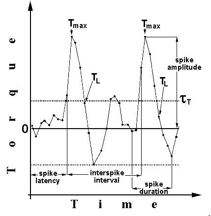
An array of data points containing two typical spikes is depicted in Fig. 10.

Fig. 10: Stretch of 33 yaw torque data points (i.e. 1.6s).
Data points are connected by lines for better illustration. Dotted lines
indicate detection thresholds. See text for details.
Once a spike is detected, its amplitude, duration and the time elapsed since the previous spike (or since the quadrant change, if one occurred between two spikes) is recorded (Fig. 10). From these data three indices are calculated: the amplitude index is calculated as (a1-a2)/(a1+a2) where a1 denotes the mean spike amplitude in the quadrants containing the pattern orientation associated with heat. The latency index is calculated as (l1-l2)/(l1+l2) with l2 being the mean time interval measured from a change into the 'hot' quadrant until the first spike in this quadrant. The ISI index is defined accordingly as the difference of the mean interspike intervals (ISI) in the 'hot' and the 'cold' sectors: (d1-d2)/d1+d2); here d2 denotes the mean distance between two spikes in the quadrant containing the pattern orientation combined with the reinforcer. Once the timing of the spikes is accounted for, one can calculate the number of spikes per time in each sector and define a number index as (n1-n2)/(n1+n2) with n1 denoting the spike frequency in the 'hot' sectors.
In addition to the force and the timing of the body saccades, the direction
of the turns might be important for a fly when performing in the described
learning paradigm. The polarity of a spike is defined as "towards
pattern" if it leads to a rotation of the arena that brings the center
of the nearest pattern closer to the very front, which is delineated by
the longitudinal axis of the fly. Accordingly, the spike polarity "from
pattern" brings the nearest quadrant border closer to the most frontal
position.
After some preliminary calculations, the following variables have been
taken into account: a polarity index, yields the fraction of spikes
towards the pattern. It is defined as (st-sf)/(st+sf) with st being the
number of spikes towards the pattern and sf the number of spikes away from
the pattern. This index had to be calculated for 'hot' and 'cold' sectors
separately.
The time elapsed from the entrance into a sector until the first spike
away from the pattern is determined as well. Obviously, this is highly
influenced by the timing of the spikes regardless of their polarity, so
the difference is calculated between the latency index for all the first
spikes towards the pattern and the latency index for all the first spikes
away from the pattern. If this polarity-latency index is positive,
the first spikes away from the pattern were generated earlier in quadrants
where the pattern orientation is associated with the reinforcer than in
the other sectors, spike frequency modulations included.